Draw a Circle on a Sphere Mathematica

3D illustration of a stereographic project from the north pole onto a plane below the sphere
In geometry, the stereographic projection is a particular mapping (function) that projects a sphere onto a plane. The projection is divers on the entire sphere, except at one betoken: the project indicate. Where information technology is divers, the mapping is smooth and bijective. It is conformal, meaning that it preserves angles at which curves meet. Information technology is neither isometric nor area-preserving: that is, information technology preserves neither distances nor the areas of figures.
Intuitively, then, the stereographic project is a way of picturing the sphere as the plane, with some inevitable compromises. Considering the sphere and the airplane appear in many areas of mathematics and its applications, then does the stereographic projection; information technology finds use in various fields including complex analysis, cartography, geology, and photography. In practice, the projection is carried out by estimator or past mitt using a special kind of graph paper called a stereographic cyberspace, shortened to stereonet, or Wulff internet.
History [edit]

Illustration by Rubens for "Opticorum libri sex activity philosophis juxta air-conditioning mathematicis utiles", past François d'Aguilon. It demonstrates the principle of a general perspective projection, of which the stereographic project is a special case.
The stereographic projection was known to Hipparchus, Ptolemy and probably before to the Egyptians. It was originally known as the planisphere projection.[1] Planisphaerium by Ptolemy is the oldest surviving document that describes it. One of its almost of import uses was the representation of celestial charts.[1] The term planisphere is still used to refer to such charts.
In the 16th and 17th century, the equatorial attribute of the stereographic projection was ordinarily used for maps of the Eastern and Western Hemispheres. It is believed that already the map created in 1507 past Gualterius Lud[2] was in stereographic projection, equally were afterwards the maps of Jean Roze (1542), Rumold Mercator (1595), and many others.[three] In star charts, fifty-fifty this equatorial aspect had been utilised already past the ancient astronomers similar Ptolemy.[4]
François d'Aguilon gave the stereographic projection its current name in his 1613 work Opticorum libri sex philosophis juxta ac mathematicis utiles (Six Books of Optics, useful for philosophers and mathematicians akin).[5]
In 1695, Edmond Halley, motivated by his involvement in star charts, published the first mathematical proof that this map is conformal.[6] He used the recently established tools of calculus, invented past his friend Isaac Newton.
Definition [edit]
Offset conception [edit]

Stereographic projection of the unit sphere from the north pole onto the plane z = 0, shown hither in cross section
The unit sphere S 2 in three-dimensional space R 3 is the set of points (10, y, z) such that x 2 + y ii + z 2 = 1. Let N = (0, 0, 1) be the "north pole", and let M be the remainder of the sphere. The plane z = 0 runs through the center of the sphere; the "equator" is the intersection of the sphere with this aeroplane.
For any point P on M , there is a unique line through N and P , and this line intersects the plane z = 0 in exactly one point P′ , known as the stereographic projection of P onto the aeroplane.
In Cartesian coordinates (10, y, z) on the sphere and (X, Y) on the plane, the project and its changed are given by the formulas

In spherical coordinates (φ, θ) on the sphere (with φ the zenith angle, 0 ≤ φ ≤ π, and θ the azimuth, 0 ≤ θ ≤ 2π) and polar coordinates (R, Θ) on the plane, the projection and its inverse are

Here, φ is understood to take value π when R = 0. Likewise, there are many ways to rewrite these formulas using trigonometric identities. In cylindrical coordinates (r, θ, z) on the sphere and polar coordinates (R, Θ) on the aeroplane, the project and its inverse are

Other conventions [edit]

Stereographic project of the unit sphere from the north pole onto the aeroplane z = −ane, shown here in cantankerous section
Some authors[7] define stereographic project from the n pole (0, 0, 1) onto the plane z = −one, which is tangent to the unit sphere at the south pole (0, 0, −1). The values X and Y produced by this projection are exactly twice those produced past the equatorial project described in the preceding department. For example, this projection sends the equator to the circle of radius 2 centered at the origin. While the equatorial projection produces no minute area distortion forth the equator, this pole-tangent projection instead produces no infinitesimal area baloney at the south pole.
Other authors[8] use a sphere of radius one / 2 and the plane z = − 1 / 2 . In this case the formulae become


Stereographic projection of a sphere from a indicate Q onto the plane E , shown hither in cross department
In general, one can ascertain a stereographic projection from any point Q on the sphere onto whatever airplane E such that
- Eastward is perpendicular to the diameter through Q , and
- E does not incorporate Q .
As long equally Eastward meets these conditions, and so for any point P other than Q the line through P and Q meets East in exactly 1 indicate P′ , which is divers to exist the stereographic projection of P onto East.[ix]
Generalizations [edit]
More than generally, stereographic projection may be practical to the unit n -sphere S n in ( n + 1)-dimensional Euclidean space E north+1 . If Q is a point of S due north and East a hyperplane in Due east n+1 , then the stereographic projection of a point P ∈ Due south n − {Q} is the point P′ of intersection of the line QP with East . In Cartesian coordinates ( x i , i from 0 to north ) on S due north and ( X i , i from ane to north) on East , the projection from Q = (1, 0, 0, ..., 0)∈ S n is given by
- .

Defining
- ,

the inverse is given past
- .

Notwithstanding more generally, suppose that S is a (nonsingular) quadric hypersurface in the projective infinite P n+ane . In other words, S is the locus of zeros of a non-singular quadratic form f(ten 0, ..., x n+ane) in the homogeneous coordinates x i . Fix any bespeak Q on S and a hyperplane Eastward in P n+one not containing Q . Then the stereographic projection of a point P in S − {Q} is the unique point of intersection of QP with E . As before, the stereographic project is conformal and invertible outside of a "small" set. The stereographic project presents the quadric hypersurface every bit a rational hypersurface.[10] This construction plays a role in algebraic geometry and conformal geometry.
Properties [edit]
The first stereographic projection defined in the preceding department sends the "south pole" (0, 0, −1) of the unit of measurement sphere to (0, 0), the equator to the unit of measurement circle, the southern hemisphere to the region inside the circle, and the northern hemisphere to the region exterior the circle.
The projection is not defined at the projection point North = (0, 0, 1). Small neighborhoods of this indicate are sent to subsets of the plane far abroad from (0, 0). The closer P is to (0, 0, i), the more distant its image is from (0, 0) in the aeroplane. For this reason it is common to speak of (0, 0, one) as mapping to "infinity" in the airplane, and of the sphere every bit completing the plane by adding a point at infinity. This notion finds utility in projective geometry and complex analysis. On a merely topological level, it illustrates how the sphere is homeomorphic to the one-bespeak compactification of the plane.
In Cartesian coordinates a point P(10, y, z) on the sphere and its image P′(X, Y) on the airplane either both are rational points or none of them:


A Cartesian grid on the plane appears distorted on the sphere. The grid lines are still perpendicular, merely the areas of the filigree squares shrink every bit they arroyo the north pole.

A polar filigree on the plane appears distorted on the sphere. The filigree curves are even so perpendicular, merely the areas of the filigree sectors shrink as they approach the n pole.
Stereographic projection is conformal, pregnant that information technology preserves the angles at which curves cross each other (run into figures). On the other hand, stereographic projection does not preserve area; in general, the area of a region of the sphere does not equal the area of its projection onto the plane. The area element is given in (X, Y) coordinates by

Along the unit circle, where 10 2 + Y 2 = 1, at that place is no inflation of area in the limit, giving a scale cistron of 1. Nigh (0, 0) areas are inflated by a factor of 4, and nearly infinity areas are inflated by arbitrarily modest factors.
The metric is given in (Ten, Y) coordinates past

and is the unique formula found in Bernhard Riemann's Habilitationsschrift on the foundations of geometry, delivered at Göttingen in 1854, and entitled Über die Hypothesen welche der Geometrie zu Grunde liegen.
No map from the sphere to the airplane can exist both conformal and expanse-preserving. If it were, and so information technology would be a local isometry and would preserve Gaussian curvature. The sphere and the airplane take unlike Gaussian curvatures, and then this is impossible.
Circles on the sphere that practice not laissez passer through the point of projection are projected to circles on the plane. Circles on the sphere that do pass through the betoken of project are projected to direct lines on the airplane. These lines are sometimes thought of every bit circles through the point at infinity, or circles of infinite radius.
All lines in the aeroplane, when transformed to circles on the sphere by the inverse of stereographic project, meet at the projection point. Parallel lines, which practice non intersect in the plane, are transformed to circles tangent at projection point. Intersecting lines are transformed to circles that intersect transversally at 2 points in the sphere, 1 of which is the projection point. (Similar remarks hold nigh the real projective plane, but the intersection relationships are unlike there.)

The sphere, with various loxodromes shown in singled-out colors
The loxodromes of the sphere map to curves on the aeroplane of the form

where the parameter a measures the "tightness" of the loxodrome. Thus loxodromes represent to logarithmic spirals. These spirals intersect radial lines in the aeroplane at equal angles, just as the loxodromes intersect meridians on the sphere at equal angles.

The stereographic project relates to the plane inversion in a simple manner. Permit P and Q be ii points on the sphere with projections P′ and Q′ on the airplane. Then P′ and Q′ are inversive images of each other in the image of the equatorial circle if and merely if P and Q are reflections of each other in the equatorial plane.
In other words, if:
- P is a indicate on the sphere, but not a 'north pole' N and not its antipode, the 'due south pole' S ,
- P′ is the image of P in a stereographic projection with the projection signal N and
- P″ is the prototype of P in a stereographic projection with the projection point S ,
then P′ and P″ are inversive images of each other in the unit circumvolve.

Wulff net [edit]

Wulff cyberspace or stereonet, used for making plots of the stereographic projection past paw

The generation of a Wulff net (circular internet within the red circle) by a stereographic projection with eye C and projection plane

Stereographic projection plots can be carried out past a computer using the explicit formulas given above. However, for graphing by paw these formulas are unwieldy. Instead, it is common to apply graph paper designed specifically for the job. This special graph newspaper is called a stereonet or Wulff net, after the Russian mineralogist George (Yuri Viktorovich) Wulff.[11]
The Wulff net shown here is the stereographic projection of the filigree of parallels and meridians of a hemisphere centred at a point on the equator (such as the Eastern or Western hemisphere of a planet).
In the effigy, the area-distorting property of the stereographic projection tin can be seen past comparing a grid sector nearly the center of the cyberspace with one at the far right or left. The two sectors have equal areas on the sphere. On the deejay, the latter has nearly 4 times the area of the former. If the grid is made finer, this ratio approaches exactly 4.
On the Wulff net, the images of the parallels and meridians intersect at right angles. This orthogonality holding is a outcome of the bending-preserving property of the stereoscopic project. (However, the bending-preserving property is stronger than this holding. Non all projections that preserve the orthogonality of parallels and meridians are angle-preserving.)
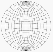
Illustration of steps 1–four for plotting a indicate on a Wulff net
For an instance of the use of the Wulff net, imagine two copies of information technology on sparse paper, i atop the other, aligned and tacked at their mutual center. Permit P be the indicate on the lower unit hemisphere whose spherical coordinates are (140°, 60°) and whose Cartesian coordinates are (0.321, 0.557, −0.766). This signal lies on a line oriented threescore° counterclockwise from the positive x -centrality (or thirty° clockwise from the positive y -axis) and 50° below the horizontal airplane z = 0. Once these angles are known, there are four steps to plotting P :
- Using the grid lines, which are spaced 10° apart in the figures here, mark the point on the edge of the cyberspace that is 60° counterclockwise from the point (1, 0) (or 30° clockwise from the point (0, 1)).
- Rotate the peak net until this bespeak is aligned with (1, 0) on the lesser cyberspace.
- Using the grid lines on the bottom net, mark the point that is 50° toward the center from that point.
- Rotate the tiptop cyberspace oppositely to how information technology was oriented earlier, to bring it back into alignment with the bottom net. The bespeak marked in step 3 is so the projection that we wanted.
To plot other points, whose angles are non such round numbers every bit 60° and l°, one must visually interpolate between the nearest grid lines. It is helpful to have a net with effectively spacing than 10°. Spacings of two° are common.
To discover the central angle between ii points on the sphere based on their stereographic plot, overlay the plot on a Wulff net and rotate the plot about the center until the two points prevarication on or near a meridian. So measure the angle between them by counting grid lines along that meridian.
-

Two points P 1 and P 2 are drawn on a transparent canvas tacked at the origin of a Wulff internet.
-

The transparent sheet is rotated and the key angle is read along the common summit to both points P 1 and P 2 .
Applications inside mathematics [edit]
Complex analysis [edit]
The complex aeroplane and the Riemann sphere higher up it
Although whatsoever stereographic projection misses i signal on the sphere (the projection betoken), the entire sphere can be mapped using two projections from distinct projection points. In other words, the sphere can exist covered by two stereographic parametrizations (the inverses of the projections) from the plane. The parametrizations tin exist called to induce the same orientation on the sphere. Together, they describe the sphere as an oriented surface (or two-dimensional manifold).
This construction has special significance in complex analysis. The point (X, Y) in the real plane can be identified with the circuitous number ζ = 10 + iY . The stereographic projection from the n pole onto the equatorial aeroplane is then

Similarly, letting ξ = X − iY be some other complex coordinate, the functions

ascertain a stereographic projection from the s pole onto the equatorial plane. The transition maps betwixt the ζ - and ξ -coordinates are and so ζ = 1 / ξ and ξ = 1 / ζ , with ζ approaching 0 as ξ goes to infinity, and vice versa. This facilitates an elegant and useful notion of infinity for the complex numbers and indeed an entire theory of meromorphic functions mapping to the Riemann sphere. The standard metric on the unit sphere agrees with the Fubini–Study metric on the Riemann sphere.
Visualization of lines and planes [edit]
Blitheness of Kikuchi lines of iv of the eight <111> zones in an fcc crystal. Planes edge-on (banded lines) intersect at fixed angles.
The set of all lines through the origin in three-dimensional infinite forms a space called the real projective airplane. This airplane is hard to visualize, considering it cannot exist embedded in iii-dimensional space.
However, one can visualize it as a disk, as follows. Any line through the origin intersects the southern hemisphere z ≤ 0 in a point, which tin so be stereographically projected to a betoken on a deejay in the XY plane. Horizontal lines through the origin intersect the southern hemisphere in two antipodal points along the equator, which project to the purlieus of the deejay. Either of the two projected points tin exist considered part of the disk; it is understood that converse points on the equator represent a single line in 3 space and a single bespeak on the purlieus of the projected disk (run across quotient topology). And so any set of lines through the origin tin be pictured as a prepare of points in the projected deejay. But the boundary points deport differently from the purlieus points of an ordinary 2-dimensional deejay, in that any one of them is simultaneously close to interior points on opposite sides of the disk (just as ii nearly horizontal lines through the origin can project to points on reverse sides of the disk).
As well, every plane through the origin intersects the unit sphere in a not bad circle, called the trace of the plane. This circumvolve maps to a circumvolve under stereographic project. So the project lets us visualize planes every bit circular arcs in the deejay. Prior to the availability of computers, stereographic projections with not bad circles oftentimes involved drawing large-radius arcs that required apply of a beam compass. Computers now make this job much easier.
Further associated with each plane is a unique line, chosen the plane'south pole, that passes through the origin and is perpendicular to the plane. This line tin can exist plotted as a point on the disk just as whatever line through the origin can. So the stereographic projection also lets us visualize planes every bit points in the disk. For plots involving many planes, plotting their poles produces a less-cluttered picture than plotting their traces.
This structure is used to visualize directional information in crystallography and geology, as described below.
Other visualization [edit]
Stereographic projection is also applied to the visualization of polytopes. In a Schlegel diagram, an n -dimensional polytope in R due north+one is projected onto an n -dimensional sphere, which is then stereographically projected onto R n . The reduction from R n+one to R north can make the polytope easier to visualize and understand.
Arithmetic geometry [edit]

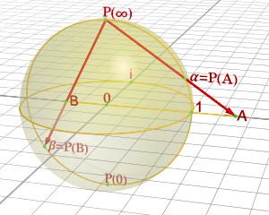
The rational points on a circumvolve represent, under stereographic projection, to the rational points of the line.
In elementary arithmetic geometry, stereographic projection from the unit circle provides a means to describe all primitive Pythagorean triples. Specifically, stereographic projection from the north pole (0,one) onto the x -axis gives a i-to-one correspondence betwixt the rational number points (x, y) on the unit circle (with y ≠ 1) and the rational points of the x -centrality. If ( m / due north , 0) is a rational betoken on the ten -axis, then its inverse stereographic project is the signal

which gives Euclid's formula for a Pythagorean triple.
Tangent one-half-angle commutation [edit]
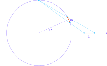
The pair of trigonometric functions (sin x, cos x) can be thought of as parametrizing the unit circle. The stereographic project gives an alternative parametrization of the unit of measurement circle:

Under this reparametrization, the length element dx of the unit of measurement circle goes over to

This substitution can sometimes simplify integrals involving trigonometric functions.
Applications to other disciplines [edit]
Cartography [edit]
The fundamental trouble of cartography is that no map from the sphere to the plane can accurately represent both angles and areas. In general, surface area-preserving map projections are preferred for statistical applications, while angle-preserving (conformal) map projections are preferred for navigation.
Stereographic projection falls into the second category. When the projection is centered at the Earth'due south n or south pole, information technology has boosted desirable properties: Information technology sends meridians to rays emanating from the origin and parallels to circles centered at the origin.
-

Stereographic projection of the world north of xxx°S. 15° graticule.
Planetary science [edit]

A stereographic projection of the Moon, showing regions polewards of sixty° Due north. Craters which are circles on the sphere announced round in this project, regardless of whether they are shut to the pole or the border of the map.
The stereographic is the just projection that maps all circles on a sphere to circles on a plane. This property is valuable in planetary mapping where craters are typical features. The set of circles passing through the indicate of projection have unbounded radius, and therefore degenerate into lines.
Crystallography [edit]

In crystallography, the orientations of crystal axes and faces in three-dimensional space are a central geometric concern, for example in the interpretation of 10-ray and electron diffraction patterns. These orientations can be visualized equally in the section Visualization of lines and planes above. That is, crystal axes and poles to crystal planes are intersected with the northern hemisphere and so plotted using stereographic project. A plot of poles is called a pole figure.
In electron diffraction, Kikuchi line pairs appear equally bands decorating the intersection between lattice plane traces and the Ewald sphere thus providing experimental access to a crystal'southward stereographic projection. Model Kikuchi maps in reciprocal space,[12] and fringe visibility maps for apply with bend contours in direct infinite,[xiii] thus deed as road maps for exploring orientation space with crystals in the transmission electron microscope.
Geology [edit]

Use of lower hemisphere stereographic projection to plot planar and linear data in structural geology, using the example of a fault airplane with a slickenside lineation
Researchers in structural geology are concerned with the orientations of planes and lines for a number of reasons. The foliation of a stone is a planar characteristic that often contains a linear feature chosen lineation. Similarly, a fault plane is a planar feature that may contain linear features such as slickensides.
These orientations of lines and planes at diverse scales can be plotted using the methods of the Visualization of lines and planes section above. As in crystallography, planes are typically plotted by their poles. Different crystallography, the southern hemisphere is used instead of the northern ane (because the geological features in question prevarication below the Earth's surface). In this context the stereographic project is often referred to as the equal-angle lower-hemisphere projection. The equal-area lower-hemisphere projection defined past the Lambert azimuthal equal-area projection is also used, particularly when the plot is to be subjected to subsequent statistical analysis such as density contouring.
Photography [edit]


"Vue circulaire des montagnes qu'on découvre du sommet du Glacier de Buet", Horace-Benedict de Saussure, Voyage dans les Alpes, précédés d'un essai sur l'histoire naturelle des environs de Geneve. Neuchatel, 1779–96, pl. 8.
Some fisheye lenses use a stereographic project to capture a wide-angle view.[14] Compared to more than traditional fisheye lenses which apply an equal-area projection, areas close to the edge retain their shape, and straight lines are less curved. Nevertheless, stereographic fisheye lenses are typically more expensive to manufacture.[15] Image remapping software, such equally Panotools, allows the automatic remapping of photos from an equal-expanse fisheye to a stereographic projection.
The stereographic projection has been used to map spherical panoramas, starting with Horace Bénédict de Saussure's in 1779. This results in effects known every bit a trivial planet (when the eye of projection is the nadir) and a tube (when the middle of projection is the zenith).[16]
The popularity of using stereographic projections to map panoramas over other azimuthal projections is attributed to the shape preservation that results from the conformality of the projection.[16]
See also [edit]
- Listing of map projections
- Astrolabe
- Astronomical clock
- Poincaré deejay model, the analogous mapping of the hyperbolic plane
- Stereographic projection in cartography
References [edit]
- ^ a b Snyder (1993).
- ^ According to (Snyder 1993), although he acknowledges he did not personally see it
- ^ Snyder (1989).
- ^ Brown, Lloyd Arnold : The story of maps, p.59.
- ^ According to (Elkins, 1988) who references Eckert, "Die Kartenwissenschaft", Berlin 1921, pp 121–123
- ^ Timothy Feeman. 2002. "Portraits of the Earth: A Mathematician Looks at Maps". American Mathematical Society.
- ^ Cf. Apostol (1974) p. 17.
- ^ Gelfand, Minlos & Shapiro 1963
- ^ Cf. Pedoe (1988).
- ^ Cf. Shafarevich (1995).
- ^ Wulff, George, Untersuchungen im Gebiete der optischen Eigenschaften isomorpher Kristalle: Zeits. Krist.,36, 1–28 (1902)
- ^ M. von Heimendahl, W. Bell and G. Thomas (1964) Applications of Kikuchi line analyses in electron microscopy, J. Appl. Phys. 35:12, 3614–3616.
- ^ P. Fraundorf, Wentao Qin, P. Moeck and Eric Mandell (2005) Making sense of nanocrystal lattice fringes, J. Appl. Phys. 98:114308.
- ^ Samyang 8 mm f/3.5 Fisheye CS Archived 2011-06-29 at the Wayback Machine
- ^ "Samyang 8 mm f/3.5 Aspherical IF MC Fish-eye". lenstip.com. Retrieved 2011-07-07 .
- ^ a b German et al. (2007).
Sources [edit]
- Apostol, Tom (1974). Mathematical Analysis (2 ed.). Addison-Wesley. ISBN0-201-00288-4.
- Brown, James & Churchill, Ruel (1989). Complex variables and applications. New York: McGraw-Hill. ISBN0-07-010905-ii.
- Casselman, Bill (2014), Feature column February 2014:Stereographic Projection, AMS, retrieved 2014-12-12
- German, Daniel; Burchill, L.; Duret-Lutz, A.; Pérez-Duarte, Due south.; Pérez-Duarte, E.; Sommers, J. (June 2007). "Flattening the Viewable Sphere". Proceedings of Computational Aesthetics 2007. Banff: Eurographics. pp. 23–28.
- Gelfand, I.M.; Minlos, R.A.; Shapiro, Z.Ya. (1963), Representations of the Rotation and Lorentz Groups and their Applications, New York: Pergamon Press
- Practice Carmo; Manfredo P. (1976). Differential geometry of curves and surfaces. Englewood Cliffs, New Bailiwick of jersey: Prentice Hall. ISBN0-xiii-212589-vii.
- Elkins, James (1988). "Did Leonardo Develop a Theory of Curvilinear Perspective?: Together with Some Remarks on the 'Angle' and 'Altitude' Axioms". Journal of the Warburg and Courtauld Institutes. The Warburg Establish. 51: 190–196. doi:10.2307/751275. JSTOR 751275.
- Oprea, John (2003). Differential geometry and applications. Englewood Cliffs, New Jersey: Prentice Hall. ISBN0-xiii-065246-6.
- Pedoe, Dan (1988). Geometry. Dover. ISBN0-486-65812-0.
- Shafarevich, Igor (1995). Basic Algebraic Geometry I . Springer. ISBN0-387-54812-2.
- Snyder, John P. (1987). Map Projections − A Working Transmission, Professional Newspaper 1395. US Geological Survey.
- Snyder, John P. (1989). An Album of Map Projections, Professional person Paper 1453. US Geological Survey.
- Snyder, John P. (1993). Flattening the World. University of Chicago. ISBN0-226-76746-9.
- Spivak, Michael (1999). A comprehensive introduction to differential geometry, Volume Iv. Houston, Texas: Publish or Perish. ISBN0-914098-73-X.
External links [edit]
- Weisstein, Eric W. "Stereographic projection". MathWorld.
- Stereographic Projection Archived 2013-03-10 at the Wayback Auto on PlanetMath
- Stereographic Projection and Inversion from Cutting-the-Knot
- DoITPoMS Pedagogy and Learning Bundle - "The Stereographic Project"
Videos [edit]
- Proof about Stereographic Projection taking circles in the sphere to circles in the airplane
- Time Lapse Stereographic Projection on Vimeo
Software [edit]
- Free and open source python programme for stereographic project - PTCLab
- Sphaerica software is capable of displaying spherical constructions in stereographic projection
- 3 dimensional Java Applet
Miniplanet panoramas [edit]
- Examples of miniplanet panoramas, majority in UK
- Examples of miniplanet panoramas, majority in Czech republic
- Examples of miniplanet panoramas, majority in Poland
Source: https://en.wikipedia.org/wiki/Stereographic_projection
0 Response to "Draw a Circle on a Sphere Mathematica"
Post a Comment